Viewing Cones and Viewing Areas
Historically, lenticular lens 3D displays were designed for multiple viewers. The calibration process adjusted the weaving to project a single viewing cone centered in front of the display. The figure below illustrates this concept for a 2-view system.

The single-viewing cone scenario described above demonstrates an important principle: the user’s z-position (distance from the display) has no effect on the view. Since light exits perpendicular to the pixel plane, the assigned view number remains constant, regardless of the viewer’s distance.
We now examine a practical scenario where each pixel’s light is distributed across multiple viewing cones. The diagram below illustrates this with two key components:
- The central viewing cone (primary optimal zone).
- Peripheral cones generated by pixels at the display edges.
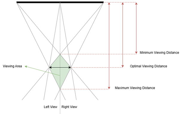
Let’s assume a viewer roughly looking from the middle of the display. The image they receive for the left and right views will be created from many viewing cones. Some of them will contain light form pixels that go perpendicular to the display plane, and this will change incrementally when we move from the center to the edges.
This multi-cone configuration establishes a well-defined viewing area with minimum and maximum viewing distances. For multiview displays, we must note that there are additional, but smaller areas with correct 3D, which enables multiple people to see the 3D effect at the same time.
For single viewer display, we must note that, While the central cone dominates the user's visual perception, which makes accurate eye-tracking in x and y dimensions crucial to avoid crosstalk, the z-position only affects angled pixel contributions. While as in the case of the multiview we have several, adjacent viewing zones, becuase this systems move the viewing cone to point always to the viewer, we don't perceive any difference when moving, despite the fundamentals being the same.